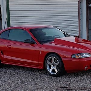
Instrument Cluster Gauge Swap How-To (with some other stuff)

mcglsr2

Well-Known Member
SN95 Supporter
Joined
Jul 4, 2011
Messages
3,410
Reaction score
40
Location
Orlando
Interested in adding in some gauges to your instrument cluster? Want to completely swap out the stock cluster but keep the same functionality? Not sure how to wire everything up?

This guide documents the modifications I am making to my 95 - you may want to do something similar but aren't sure where to start. I hope the information I have provided here is helpful to you and answers/addresses questions you may have. There is a lot of information here, and thus a lot of words. I will attempt to keep the wording as brief as possible while still conveying the necessary information. I apologize in advance for any subsequent failures in this department.


The focus of this guide is on the instrument cluster; however, I did several other modifications/additions at the same time. I have included those items here as well as they may be informative to you. This guide is not meant to be a "thou must do this" set of steps, but rather as an indication of the things to address. Please feel free to modify these schematics to suit your needs.

I am currently working through these changes, documenting it as I go. Therefore some sections may not be completed yet. I will update them as soon as I can.


*Disclaimer*
Having said the above, I take no responsibility for the changes you make to your vehicle. This guide is provided as an example of what a person has done - changes/modifications you choose to undertake, whether that be during the following of this guide, is entirely your responsibility. Please use your brain. While these changes work for me, your situation (read: car) may be different from mine. Furthermore, this guide is specific to my car, a 95 Mustang GT. It should be applicable to other years as well, particularly the 94 and possibly earlier years. It may also be applicable (though not exactly correct regarding pin-outs and wire color) to later model years. I advise you to confirm your stock connectors/pins/wire colors before proceeding, though the general concepts here should still be applicable across many model years.

Table of Contents
01: This Introduction
02: Initial Concept / What is Changing?

03: What You Will Need

04: Wiring Diagrams and How to Read Them

05: Stock Cluster Harness
06:
Cluster

07: Pod

08: Radio Bezel & Widebands

09: Footwell and Door Switch Lighting

10: Dash Harness

11: Battery Relocate, Kill Switch & Trunk Lighting

12: Summary/Conclusion
 
OP
OP
mcglsr2

mcglsr2

Well-Known Member
SN95 Supporter
Joined
Jul 4, 2011
Messages
3,410
Reaction score
40
Location
Orlando
Initial Concept/What Is Changing?


This guide deals with modifying and changing certain key aspects of the car. Specifically, swapping out the stock instrument cluster for aftermarket gauges. In addition to this, there are a number of other wiring/dash changes I wanted to make either because of personal preference and/or because I use this car for road racing. You may agree with some changes, none of the changes, or all of the changes. I have chosen specific components for certain modifications - but choice on component does not reflect the "correct" choice, just my choice.

So while I started this how-to under the guise of a cluster to aftermarket gauge swap, I have expanded it to include other things. Those things are (in no particular order):


  • Stock instrument cluster swap to all Auto Meter gauges
  • Moving the warning (idiot) lights from the stock cluster to clock pod (referred to as Pod)
  • Installing a battery kill switch - I decided not to do this at this time, though the wiring diagrams will still show how to do it.
  • Moving the battery from the stock location to the trunk behind the passenger seat - I changed my mind and put the battery behind the passenger seat rather than the trunk
  • Wiring in Zeitronix Wideband controllers
  • Adding additional gauges beyond the cluster swap
  • Adding LED footwell lighting
  • Adding LED trunk lighting - I decided not to do this due to time constraints, though the wiring diagrams will show how to do it
  • Adding LED hood lighting - I decided not to do this due to time constraints, though the wiring diagrams will show how to do it
  • Adding LED power window/door lock switch lighting
  • Wiring in dimmer control for cluster/LED lighting
  • Adding a new fuse box for the gauges
  • Fan HI override switch
  • Wiring in a TPMS

I am not starting "fresh" - my car has already undergone some of the items from the list above. However, I have decided to start from scratch and do a proper job of it, so existing items from that list will be re-evaluated and wired/installed accordingly.

My goal is to provide fused power to the gauges without re-using an existing car wiring - I don't want to have to deal with fuses and what else in the car may be using those power circuits. The additional wire weight is negligible (besides, my car is not full race yet, so I'm not too concerned with extreme diets) and maintenance will be easier. I do, however, re-use other existing car wiring for things like tach signals, fuel level signals, etc. Things that the ECU would be reporting to the stock cluster that the new gauges need to make use of. Auto Meter instructions call for each gauge to have its own fuse, thus each gauge gets its own dedicated fused power feed.

For components that do not specifically require fused power (such as the wideband controllers or shift light) - I will make use of existing fused power circuits. Specifically in the dash, as the power feed there that used to feed the stock gauges is no longer being used for that, so I will make use of those power feeds for other things if applicable.
 
OP
OP
mcglsr2

mcglsr2

Well-Known Member
SN95 Supporter
Joined
Jul 4, 2011
Messages
3,410
Reaction score
40
Location
Orlando
What You Will Need


Here is a listing of all the parts/components I used, and part numbers if I have them. If you want to use other gauges or components, go for it. Just keep in mind that I wired things based on the components that I have - if you use different components you may have to modify the wiring diagrams/schematics accordingly.

Note: I will not be maintaining these links so if, over time, some become broken, I apologize. Having said that, the part number that I reference is the actual part number, so if the link is broken, please go to the manufacture's website and search for the part number I specified.


Instrument Cluster & Pod:

  • Instrument cluster bezel (Auto Meter part #10008)
  • Fuel Level Gauge, universal; 2-1/16" (Auto Meter part #3610)
  • Water Temperature Gauge, with warning alert; 2-1/16" (Auto Meter part #3654)
  • Tachometer; 3-3/8" (Auto Meter part #3697)
  • Speedometer, 160 MPH programmable; 3-3/8" (Auto Meter part #3688)
  • Oil Pressure Gauge, with warning alert; 2-1/16" (Auto Meter part #3652)
  • Voltmeter; 2-1/16" (Auto Meter part #3691)
  • LED Dimmer control (Auto Meter part #9114)
  • Pod mount (Auto Meter part #10001)
  • 12V LEDs in amber, red & green (sourced from led-switch.com)
  • 12V bulbs in red & green
  • ~510 Ohm resistor (for alternator charge indicator light)

Other Gauges:

  • Oil Temperature Gauge, with warning alert; 2-1/16" (Auto Meter part #3640)

Other Components:

  • Shift Light (Ecliptech Shift-i)
  • Toggle Switch for Fan Hi override, with LED power-on light
  • Wideband Controller (Two Zeitronix Zt-3, left bank & right bank)
  • TPMS Retrofit (Orange P409S)

Battery Relocation:

  • Battery Kill Switch (Flaming River part #FR1013)
  • Battery relocation box (UPR part #9005) - note that I did not use this box as I did not do a trunk mount; instead I used the box below:
  • Battery Hold Down for Odyssey PC680

All the Rest of the Stuff:

  • Harness connectors (Molex type sourced from CE Auto Electric; 12-pin [x1], 9-pin [x2], 6-pin [x1], 3-pin [x3] & 2-pin [x7])
  • Reed switches for hook/trunk lighting
  • Wire in various color (sourced from wirebarn.com in 25ft spools, you may require more length)
  • Fuse Box (Blue Sea Systems part #5026)
  • Relays (sourced from wirebarn.com)
  • Good wire strippers
  • Good soldering iron (recommended), or crimp connections if you can't solder or choose not to
  • Various tapes, such as electrical tape (3M Super 33+), painters tape for temporary labels, harness tape, etc.
  • Zip ties
  • Heat Shrink tubing
  • Weather Pack connectors (sourced from DIY Auto Tune)
  • Assortment of spade terminals, ring terminals & fork terminals
  • Other items that aren't mentioned here but are later on in the specific step(s)

For wiring, I used mostly 20 gauge AWG. For the battery relocation, I opted for 1/0 for the positive and multiple wires of 4 AWG for the Negative. The posts where the work gets done will have additional information on the items that were used.

If you have any questions on why I chose certain components, or what I was thinking, feel free to post up a question.
 
OP
OP
mcglsr2

mcglsr2

Well-Known Member
SN95 Supporter
Joined
Jul 4, 2011
Messages
3,410
Reaction score
40
Location
Orlando
Wiring Diagrams and How to Read Them


In order to understand the wiring diagrams I am about to provide, you will need this Legend. I tried to use standard electrical symbols where it made sense, but there are still some conventions I decided on that may not be familiar to you (for example, I treated the LEDs as components rather than using the diode electrical symbol). This should help:

00_Legend.png


And here are the rest of the diagrams. Each diagram depicts 1 or more components or connections. The idea is that I can start with the first wiring diagram and construct it. Then construct the next diagram. Then the next. So on until they are all "built." Then, theoretically, I should be able to just plug everything in together it will magically work. Theoretically ;)


02_Cluster-Harness_to_Cluster.png


01_Cluster-Harness_to_Pod.png


03_Cluster_Fan-Switch.png


04_Pod.png


05_Console_Wideband-amp-ECU.png


06_Interior-Lighting.png


This next one is a little hard to see due to it's larger size. I have linked it to my Photobucket account where you should be able to zoom in on it. Just click the image to head over there.


08_Kill-Switch_Trunk-Lighting.png


For reference, this is what the female portion of a connector looks like:

IMG_3981.jpg


Female refers to the metal connector part, NOT the plastic outer part. The plastic part is actually opposite. Here's an example of a female connector. Notice the plastic part is actually male, but the metal part (the part that matters) is female. Thus this is a female connector:

IMG_3987.jpg
 
OP
OP
mcglsr2

mcglsr2

Well-Known Member
SN95 Supporter
Joined
Jul 4, 2011
Messages
3,410
Reaction score
40
Location
Orlando
The Cluster Harness


The Cluster Harness is pretty straight-forward. Basically find the correct pin, splice in the wire and you are done.

I had a bunch of wires there from when I put the aftermarket cluster in previously, so for me it was a matter of converting the wire to the correct color according to the wiring diagram. Here's what I ended up with for now:

IMG_3977.jpg


The grouping of wires clumped together on the left side of the steering column are the ones that connect to the new Cluster. The grouping on the right side of the column is for the pod. You'll notice the wires for the Pod are a lot longer - that's because they need to reach over to where the Pod sits. The purple and gray wires heading over to the center are for the engine sensors. I don't have the connectors yet, so I just taped the wires together until the connectors arrive.

Here's a close-up of the left Harness connector (the black one). I wrapped electrical tape around the connector because the pins are exposed on one side.

IMG_3978.jpg


And then the left side:

IMG_3979.jpg


You may notice a wire starting off as purple and then turning in to orange - this is an example of where I had previously spliced the wire but then changed over to the new color based on the wiring diagram. If I was starting fresh, I would have used the wiring diagram color all the way to the stock cluster harness. For me, it wasn't worth ripping out the old splice just to change the color - so I changed the color further down the wire where it was much easier to do so.

Once I get the connectors on, I'll zip-the all the wires so they are a little neater. Also, I did not install the Shift Light yet as I'm not sure how to mount it. However, I did leave a power feed and tach signal lead that I can splice in later.

Just about done with the Cluster Harness, added in the connectors:

IMG_3991.jpg


IMG_3992.jpg


A lot neater looking now! The only thing left is the Shift Light. I made up a bracket to hold it in place - it's currently drying with a coat of spray paint on it. Tomorrow I will wire the Shift Lift in and the Cluster Harness will be complete.

The Shift Light installed; I made a bracket out of some aluminum to hold it down (via a screw, some washers and a nut), and passed the wires through the top of the dash:

IMG_4000.jpg


IMG_4002.jpg


IMG_4001.jpg


And that's it for the Stock Cluster Harness. It's done, ready for the Cluster and Pod to be plugged in.
 
OP
OP
mcglsr2

mcglsr2

Well-Known Member
SN95 Supporter
Joined
Jul 4, 2011
Messages
3,410
Reaction score
40
Location
Orlando
The Cluster


For the new Cluster, I painted it white to match my interior. Here it is with the gauges installed. I kept the same gauges that are in the stock cluster. Auto Meter makes 3 different configurations for the bezel - I used the 6-gauge version. This works well for a stock swap. There's also a 4-gauge version that lets you run the larger 5" tach & speedo with 2 smaller 2-1/16" gauges (probably your water temp and oil pressure?) if you wanted something more race-focused. I wanted to keep the fuel level gauge because I still drive the car on the street and didn't want to mount it anywhere else, so 6-gauge version for me.

The fan hi switch is the black thing on the bottom left.

IMG_3964.jpg


On the backside, the only wires I have in place are those for the left turn signal, right turn signal and hi beams.

IMG_3965.jpg


Alright, before jumping in to the work, I need to talk about the Speedo and Tach for a minute. The other gauges I used all have a connector pigtail that comes with them, with the wire colors I depicted in the diagrams. So which wire does what is straight forward. Just follow the colors in the diagrams. The Speedo and Tach, however, are different. They do not have a pigtail, but rather a number of spade connectors on the back side. I realize I didn't include labels in the diagram (which I will correct shortly), so in the meantime I'll list it out here.

The Tach has four connectors: GND, +12V, SIG and LAMP, all pretty self-explanatory. LAMP is for the gauge LED lighting. So, on my diagram, these are the color wires: GND --> Black; +12V --> Red; SIG --> Yellow; LAMP --> White.

The Speedo is a little more complicated. It has 5 connectors: GND, +12V, SIG, LAMP and OUT. The first four are the same as the Tach (with an exception), and the last, OUT, is not used. So, GND --> Pink; +12V --> Red, SIG --> Gray; LAMP --> White. The GND is the difference - notice it is Pink and not Black. The reason for this is that I originally had issues with the Speedo bouncing around. It was not smooth. The needle, while mostly on the right speed, would twitch a lot. I suspect this is due to interference in the VSS SIG and the GND I was originally using. When I looked again at the wiring diagram, it looked to me that the stock Speedo used the same GND as the VSS unit. So I decided to do the same this time hoping to fix it. In my Cluster, GND goes to a good chassis ground. For the Speedo, however, Pink goes to the GND that the original Speedo used, so it goes back to the Cluster Harness. That's why the difference in color, so I didn't confuse it's "special nature."


Following my wiring diagram for the console, I end up with this:

IMG_3970.jpg


I do not have the connectors yet, so I can't finish off the wiring. I taped off the groupings of wires that belong to each connector. Here's a close-up of the fan hi switch:

IMG_3971.jpg


So I think I am done for now, I'll wrap everything up when the connectors arrive. I'll also finish off the wires with some harness tape.

Connectors installed on the Cluster:

IMG_3983.jpg


IMG_3984.jpg


I may wrap the whole thing in harness tape, don't know yet. This is it for the Cluster for now. Just waiting on other things to complete before it gets installed.

I decided not to wrap it with tape. It was fine the way it was. Last step was to simply plug in the three connectors and screw it back in place:

IMG_4045.jpg


And done!
 
OP
OP
mcglsr2

mcglsr2

Well-Known Member
SN95 Supporter
Joined
Jul 4, 2011
Messages
3,410
Reaction score
40
Location
Orlando
The Pod


Alright, so now we come to what I call the Pod. The downside to the Auto Meter bezel is that there are no provisions for the warning (idiot) lights. I suppose I could have drilled a bunch of little holes somewhere, perhaps over by the defroster switch (had I not already been using that area for my fan switch), but it would end up grouping the LED's pretty close together. Labels probably would not be possible.

So, what to do about the idiot lights? I want to keep them, there are some that are quite important (low coolant, ABS problems, MIL, etc.). My stock clock pod thing was broken, so I figured I could move the idiot lights over there. I got an Auto Meter dual gauge pod, decided to use up the left side for my lights (this is actually my 3rd attempt at this pod, and I hope final). I created a mock of where the lights will go:

IMG_3976.jpg


You might notice a couple things. I used bulbs for a couple of the lights - Air Bag, BATT, and Coolant Pressure. The reason for this is that the bulbs play an integral role in the way the circuits work. So rather than risk screwing up the circuits with an LED, I kept the bulb. The other circuits are pretty straight-forward and can be done via LED. I used 12V LEDs so I didn't have to bother with resistors.

Also, I kept a couple of the warning lights that I truly don't care about, such as the Air Bag and Seat Belt ones. The Air Bag must be kept because if the bulb is removed or burned out, it will chime. I haven't removed the Air Bag module yet even though I don't have any air bags, so the easiest thing is just to leave the bulb. I was tempted to hide the bulb under the Pod, however if the bulb burned out it would be a huge pain to get to it. So I made the bulb green, and found a place for it. As for the Seat Belts, same thing. Not sure about that one, I may end up cutting the wires to disable the LED. We'll see. The Coolant Pressure bulb is a new warning light - it's a Longacre product. The sensor triggers the light of coolant pressure drops (as in there's a coolant leak at the track). RichV suggested this light and I think it's a great idea.

Lastly, and this is super important if you want your alternator to work, you *MUST* use a resistor between the two wires of the BATT bulb (which is the charge problem indicator light). If you omit this resistor, you will have issues. I think I used a 530 Ohms resistor because I couldn't find a 510 at the time. This is okay, as long as it's close to 510. If you can find a 510, use that. Just look at the wiring diagram for that bulb and be sure to follow it.

This is the Pod with the LEDs/bulbs & gauge installed:

IMG_3973.jpg


Again, following my wiring diagram:

IMG_3974.jpg


...and again, I didn't have the connectors yet. So I taped off the grouping of wires, awaiting the arrival of them. Done with this for now.

The connectors added to the pod wiring:

IMG_3982.jpg


I haven't decided yet if I'm going to wrap the wires in harness tape yet. I suspect I will just to make sure there are no issues from any possible abrasion. Either way, the Pod is done and ready to be installed. It now waits for other things to be completed.

Here's the Pod as it it is finally installed:

IMG_4030.jpg


This wraps up the Pod section.
 
OP
OP
mcglsr2

mcglsr2

Well-Known Member
SN95 Supporter
Joined
Jul 4, 2011
Messages
3,410
Reaction score
40
Location
Orlando
The Radio Bezel & Widebands


I was original going to move things around in the radio bezel, but due to time constraints I decided to keep things in the same spot. At the bottom below the radio is where the dual wideband gauges will go, and a reserved spot for whatever I want in the future, maybe a fuel pressure gauge or perhaps a diff temp gauge. Not sure at this point, so I will just leave it vacant.

Here's the bezel - not too exciting really:

IMG_4406.jpg


And installed:

IMG_4449.jpg


IMG_4453.jpg


Okay, moving on to the widebands. I've flip-flopped here quite a bit. At first, I was going to run dual Zeitronix Zt-3's, but then decided I wanted the ability to run logging. So I sold one Zt-3 and bought a Zt-2. Now, I've decided I'm going to run a MegaSquirt in the future, so I no longer need the logging from the Zt-2 (as I will be logging in MS), and I don't want the added hassle/complexity of the Zt-2, so I'm considering selling it and getting another Zt-3. I may just end up using the Zt-2 because I have it now, but literally will not be using like 90% of it's capability, which seems like a waste to me.

I'll post an update here once I figure out what I'm going to do.

Okay, so I decided on two ZT-3's, I'll use Mega Squirt for my logging. So here are the two ZT-3's wired into their harness:

IMG_4479.jpg


There are 3 connectors: 1 is for the power & ground, another is for the left & right simulated narrow band outputs that go to the stock ECU, and the 3rd is a single Weatherpak that will feed the Mega Squirt with analog wideband output (connector 2 will then be disconnected).

They are installed in the car, and hooked up to the ZR-1 gauges (one gauge reads 14.7 because the O2 sensor isn't hooked up yet):

IMG_4512.jpg


And that's it for this section!
 
OP
OP
mcglsr2

mcglsr2

Well-Known Member
SN95 Supporter
Joined
Jul 4, 2011
Messages
3,410
Reaction score
40
Location
Orlando
Footwell and Door Switch Lighting


The door switches each have red LEDs in them that will come on when the illumination circuit is turned on. Here are the switches, note the small orange and black wires - these are for the LEDs:

IMG_4478.jpg


I had some switch housing things fabbed up, and I have to say they certainly look fantastic. In this pic, the left side is the driver-side, with switches for driver window, passenger window, door lock & power mirrors. The right side is the passenger side, with passenger window and door lock.

IMG_4490.jpg


For the passenger window and door locks, I didn't want to re-use the stock wiring setup, since it switches ground and positive and is a general pain to replace switches unless you use specialized switches (and this gets extra tricky because there are 2 switches for each - one on each door - that can conflict with each other). Alas, I am not using specialized switches. So I re-purposed the existing wires and decided to use relays to control the door locks (1 relay for lock, 1 for unlock) and relays to control the passenger window (1 relay for up, 1 for down). These switches just switch GND.

IMG_4507.jpg


Cutting out the stock switch interface, and wiring in my new switches:

IMG_4516.jpg


IMG_4517.jpg


And with the switches installed, when turning on the parking/head lights, there is red illumination around the switch "hat":

IMG_4524.jpg


I also added an LED to the passenger side foot well, here's a shot from the floor up to the underside of the glove back area, you can see the black plastic tab thing that holds the LED and attaches to the lower glove box support:

IMG_4521.jpg


And a bad pic of the LED lit up with the parking/head light switch on - it looks kind of weird here but in person looks pretty nice, it's quite subtle:

IMG_4522.jpg


The power window wiring on the driver side is different from the passenger side - since there is only the 1 switch there's no need for a relay. I used a DPDT switch, rated at 25A (the window motor fuse is 20A). The switch just switches BATT/GND depending on whether it's up or down:

IMG_4483.jpg


The rest of the driver side is just taping into the existing wires there that send the GND signals to the relays mounted in the passenger door. The driver foot well LED hasn't been mounted yet, but it will work and look the same as that of the passenger side.

This section is done!
 
OP
OP
mcglsr2

mcglsr2

Well-Known Member
SN95 Supporter
Joined
Jul 4, 2011
Messages
3,410
Reaction score
40
Location
Orlando
The Dash Harness


The Dash Harness is the guy that ties everything together. I estimated the length by take a spool of wire and stretching it across the dash. I picked a good length based on my planned routing, and went with that. Here is the Dash Harness laid out on the floor, and I'm starting to wrap it with harness tape:

IMG_3989.jpg


And here it is finished up. There are various connectors attached and leads for the LED door switch lighting (which don't have connectors on them yet, not sure what I'm doing with them):

IMG_3999.jpg


This next bit here is the fuse panel. The gauges that require fused power feeds attach to the fuse block here. There are also two relays - one for the Fan Hi switch, and the other that feeds power to the fuse block on Start/Run Ignition. Lastly, the Auto Meter LED Dimmer is attached on the left side:

IMG_3993.jpg


IMG_3994.jpg


And this is where the fuse panel is going to live:

IMG_3995.jpg


And here it's starting to get wired up:

IMG_3998.jpg


The next step is to install the Dash Harness and fuse panel in the car.

The Dash Harness installed; here is the Cluster connection:

IMG_4003.jpg


As it runs under the HVAC controls:

IMG_4004.jpg


And then the fuse panel section, awaiting the fuse panel:

IMG_4005.jpg


The fuse panel all wired up:

IMG_4024.jpg


And with the protective cover on the fuse block:

IMG_4025.jpg


This is pretty much it for the Dash Harness. There are other things that will connect to, such as the door switch lights, but I'll show those connections in their respective posts.
 
OP
OP
mcglsr2

mcglsr2

Well-Known Member
SN95 Supporter
Joined
Jul 4, 2011
Messages
3,410
Reaction score
40
Location
Orlando
The Battery Relocate, Kill Switch and Trunk Lighting


I'm replacing the stock battery with an Odyssey PC680 (which is a dry cell, 15lbs motorcycle battery that supposedly is juuuuuuust good enough for a car - we'll see). I'm also relocating the battery to inside the car for several reasons: better weight distribution, removes the battery from a heat source (the engine), and I need the stock battery location for some other stuff.

If you plan on moving the battery to the trunk rather than in the cockpit, this guide still applies, you will just need longer cable. I'm using 1/0 AWG for the main feed, which may be a little overkill for the (short) distance I moved the battery but I don't feel like re-doing this later so I opted to land on the conservative side. Since most relocate kits (like UPR's) comes with 4 AWG cable, I suspect you could use that or anything above it and not have any issues, regardless of where you put the battery.

In addition to relocating the battery, I am running new cable to the starter and new cable to alternator, increasing the gauge on each. Because of the battery's small size, I really want to make sure the starter gets as much juice from it as it can without having to overcome too much resistance. So I'm using 4 AWG to the starter, and then upgrading the alternator to 6 AWG (I think stock is 8 AWG).

But first, the battery; I used steel 1/4" rivnuts for the battery hold-down:

IMG_4100.jpg


And then installed the battery/battery hold-down; I shifted it towards the center of the car for better weight distribution and because my roll bar has a diagonal brace that goes down to the left side and I didn't want it interfering with the battery:

IMG_4106.jpg


I ended up using a 250 Amp ANL fuse in between the battery and the main feed to the rest of the car, and started routing the cable around to where the kill switch will be. The majority of the cable will be under the carpet when it goes back in.

IMG_4114.jpg


IMG_4118.jpg


The kill switch will be located between the dash and driver side A pillar - it's a push-off type and I want it accessible to anyone outside the car while at the track (windows are down at the track) in case I am unable to get to it. No kill switch at this time.

The alternator cable that is getting reworked:

IMG_4119.jpg


I started by adding the new fusible links - the stock cable is 8 AWG I think, which means the two fusible links that connect to the fuse box are 12 AWG. Since I'm using larger, 6 AWG cable for the alternator, I installed two 10 AWG fusible links (fusible links should be 4 numbers smaller than the wire size they are protecting; e.g.: 6 AWG + 4 = 10 AWG).

IMG_4127.jpg


Planning out the wiring for the starter:

IMG_4419.jpg


Ran the 1/0 cable from the battery through the firewall and under the front fender (it will be covered by the splash shield). It terminates into a splitter, with the smaller gauge heading off to the starter, and the other 1/0 heading to the jumper studs where the battery used to be:

IMG_4421.jpg


The jumper studs all wired up; I cut the stock battery terminal off the ground cable, crimped on an eye, and attached it to the jumpers. I also ran an additional ground cable from the jumper over to the strut tower.

IMG_4427.jpg


IMG_4428.jpg


And for a quick reference, this is how it's wired - note that this is a high level diagram just to show how things are connected:

Batt_wiring.png


Some folks have questioned my choice to use 4 gauge for the starter cable - for my sake I hope they are wrong (because I don't want to replace it again). I think I should be okay, but I guess I'll find out when I try to start the car... :-/

And that's pretty much for the battery wiring, this section is done.

UPDATE: I have since tried starting the car with the PC680. The car starts. When the battery is at lower voltage, or warmer, the starter does drag a little; however, I think this is due to the capacity of the battery and *not* the gauge wire that I used. I feel confident that for the runs I did, the gauges I used are more than adequate.
 
OP
OP
mcglsr2

mcglsr2

Well-Known Member
SN95 Supporter
Joined
Jul 4, 2011
Messages
3,410
Reaction score
40
Location
Orlando
Summary/Conclusion


As things become completed, I'll post them here as a wrap-up.

Here's the Pod and Fuse Panel in place:

IMG_4032.jpg


And now with the fuse panel cover in place:

IMG_4033.jpg


IMG_4034.jpg


With the Cluster in place:

IMG_4044.jpg


IMG_4047.jpg


IMG_4048.jpg


Things are starting to come together:

IMG_4344.jpg


IMG_4345.jpg


IMG_4346.jpg


IMG_4436.jpg


IMG_4437.jpg


The dome light:

IMG_4469.jpg


Dome light on and driver-side map light on:

IMG_4471.jpg


IMG_4465.jpg


IMG_4512.jpg


IMG_4519.jpg


IMG_4524.jpg


So, there are a bunch of other things to do on the car, but as far as the instrument wiring and ancillary items off of that go, it's pretty much wrapped up. If there's any questions or anything please don't hesitate to drop me a line.
 

DavidBoren

Active Member
Joined
Aug 20, 2014
Messages
643
Reaction score
5
Location
Pacific Northwest.
I don't want to mess anything up or p!ss in your cheerios by posting before you are done, but it looks like you are going through a good deal of effort to provide us with a very informative write-up. Thank you. If you don't want people replying quite yet, just let me know and I will delete it.

I like the way you are going to repurpose the fused power supply to meet your needs. And your disclaimer is very thorough. I got a good chuckle out of it. The sad kind of chuckles, because you shouldn't have to have a disclaimer at all. But people are stupid and you have to protect your @ss.

Looking forward to seeing this write-up when it's completed. Keep up the good work, and thanks again for taking the time to do this.
 
OP
OP
mcglsr2

mcglsr2

Well-Known Member
SN95 Supporter
Joined
Jul 4, 2011
Messages
3,410
Reaction score
40
Location
Orlando
I don't want to mess anything up or p!ss in your cheerios by posting before you are done, but it looks like you are going through a good deal of effort to provide us with a very informative write-up. Thank you. If you don't want people replying quite yet, just let me know and I will delete it.

I like the way you are going to repurpose the fused power supply to meet your needs. And your disclaimer is very thorough. I got a good chuckle out of it. The sad kind of chuckles, because you shouldn't have to have a disclaimer at all. But people are stupid and you have to protect your @ss.

Looking forward to seeing this write-up when it's completed. Keep up the good work, and thanks again for taking the time to do this.

Thanks, and posts are welcome. I reserved what I needed. Just for clarification, the gauges themselves do not repurpose existing fused car wiring, since each gauge needs its own fuse. Otherwise, all other existing car wires are used (meaning tapped for signal) - lol I don't know if that's clear, maybe I don't understand what you are saying. It's been one of those days ;)
 

DavidBoren

Active Member
Joined
Aug 20, 2014
Messages
643
Reaction score
5
Location
Pacific Northwest.
No, you are perfectly clear with what you are doing. The new gauges require their own new fused power source(s). So that leaves you with the old (original/oem) fused power wires for the gauges you removed. You are going to use the old (oem) fused power supply for your wideband o2 sensor and your shift light. I am picking up what you are laying down.
 
OP
OP
mcglsr2

mcglsr2

Well-Known Member
SN95 Supporter
Joined
Jul 4, 2011
Messages
3,410
Reaction score
40
Location
Orlando
No, you are perfectly clear with what you are doing. The new gauges require their own new fused power source(s). So that leaves you with the old (original/oem) fused power wires for the gauges you removed. You are going to use the old (oem) fused power supply for your wideband o2 sensor and your shift light. I am picking up what you are laying down.

Werd :thumbsup:
 
OP
OP
mcglsr2

mcglsr2

Well-Known Member
SN95 Supporter
Joined
Jul 4, 2011
Messages
3,410
Reaction score
40
Location
Orlando
Alright, I updated a number of the posts. The Dash Harness and Pod are done now, and assembled back into the car. I updated the Summary/Conclusion post to show the completed pics of the Pod and Fuse Panel in place.

The Cluster is waiting to go in for the arrival of the kill switch, as I will need to access the area back there to run some wires I think. So that will be coming soon.
 
OP
OP
mcglsr2

mcglsr2

Well-Known Member
SN95 Supporter
Joined
Jul 4, 2011
Messages
3,410
Reaction score
40
Location
Orlando
Updated the Cluster section with a "done" pic, and updated the Summary/Conclusion section with some finished pics of the Cluster in place.
 

Kboss87

Member
Joined
Aug 19, 2013
Messages
205
Reaction score
0
Location
Southeastern, PA
Wow, very cool. Not something I will be personally doing, but I enjoyed the read and learned a few things.

Thank you for taking the time to make this thread.
 

Forum statistics

Threads
77,542
Messages
1,504,555
Members
15,001
Latest member
Markstang73

Members online

Top